
In todays post I will discuss the impact of rework on the overall FAB cycle time.
Rework can happen for various reasons and at different process steps. Most common it occurs after a lot has been processed at a photo step. The picture below shows a typical scenario
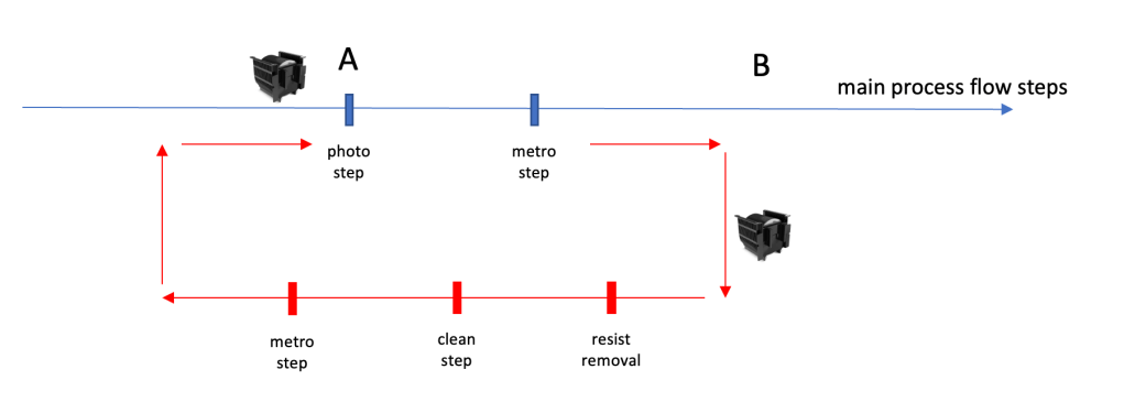
After a lot was processed at the photo step “A”, typically it will be measured at a metro(logy) step to see if the photo step was done within the desired specifications. If not, the whole lot or some wafers of the lot will be send into the red depicted “rework loop”.
There are different implementations of this in the real world. In some FABs the rework wafers will be physically split into a new carrier and the good wafers will wait at point “B” until the rework wafers are back. If this happens there will be additional sorter steps to execute the split and later the merge. These are not in the picture above, but both will consume wait time and process time, additionally to the times the rework wafers will need until they get back to point “B”
Another scenario in more advanced FABs will keep all the wafers in the same carrier and send the full lot through the rework loop. In this approach there are 2 possible execution flows:
- one where only the “bad” wafers get processed in the rework loop steps
- one where no matter what, the complete lot (all wafers) get the rework process.
Obviously all this different versions will have different cycle times – and therefore a different impact on the overall FAB cycle time.
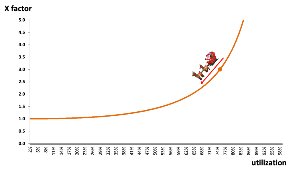
In general any rework is a hint on missing stability in the overall process. Any rework move will consume capacity on the involved processing equipment. Typically this is most impactful on the Photo equipment itself. For example, if the average rework rate in a FAB on all Photo steps is 3%, this adds 3% of tool utilization and likely a few more cascade breaks to the dispatch list or schedule. Since Litho Tools are usually some of the highest utilized tools in the factory, this will drive their utilization even more up and therefore the average lot cycle time of all lots at the photo steps will go up. This effect was already discussed in earlier posts.
On top of this “higher Utilization drives higher cycle time” effect on the photo tools themselves, the effect might be there also on all other involved tools. The impact there is likely less, since the base utilization of the non photo tools is probably lower.
So, how much adds the rework processing loop to the FAB cycle time ?
To calculate this in detail, we would need the exact data from the FAB of interest, but here is a simple formula which should work for a decent estimation:

Let’s put a few example numbers together:
Lets assume the FAB of interest has 30 mask layers (photo steps) and has a base cycle time of 60 days (2 days per mask layer).We see an average rework rate of 3 %.
How much is the typical time a lot spends in the rework loop ?
This depends as discussed on the exact form of the rework and the logistics around. I think typical numbers for a resist removal will be in the 10 – 20 minute range. Clean steps depend on batch or single wafer clean, but lets assume another 30 minutes. Additional metrology and possibly sorter steps might add another 30 minutes process time.
To keep it simple, lets assume all the rework route related process steps accumulate 1.5h of processing time. The key missing part is how much wait time will the average rework lot accumulate at each step ?
This depends heavily on the priority the rework lots will get (and of course the overall tool utilization of the rework tools). Most FABs I have seen use a rather high priority for rework lots – so lets assume they run with an x factor of 2. This will lead to a cycle time of about 3h for the rework loop, plus the second time through photo and the following metro step.
A good scenario could be an about 5 – 6 h adder for each rework round per lot. If the priority for rework lots is not very high it can be easily 8 to10h. As a matter of fact, I have seen rework rout cycle times greater 12h …
Let’s apply this assumptions to the red part of the formula:
3% x 30 x 6h –> 5.4 hours
The additional cycle time due to higher photo tool utilization is likely anything between 15 and 30 minutes per photo layer, so a total of possibly around 10h in my example factory. If we use the formula above, the original overall 60 days FAB cycle time will be increased by 0.5 .. 1.0 days with the given assumptions. Of course the impact will change if the rework rate is higher or the rework loop cycle time is significantly extended.
Summary: As long as rework rates are reasonably low and the time lots spend in the rework loop is short there is a small impact.
If you are interested in the topic of FAB cycle time reduction – I strongly recommend to head over to

In their newsletter (volume 23, No. 6) is an excellent “FAB Cycle Time Improvement Framework” discussed – great read !
Since this will be very likely the last post in 2022 –
I wish all my readers a few quiet days to recharge and a successful 2023 !

Thank you so much for the recommendation, Thomas. I read your post and was very pleased to find your kind reference to my latest article at the bottom. I enjoyed this piece. I don’t know as much about rework as I probably should. Thank you and Happy New Year!
LikeLiked by 1 person