
Today I like to discuss another potential FAB performance detractor – time links or controlled queue time zones. These got introduced to the more advanced process flows to avoid negative impact from long queue times between different process steps. Typical reasons for controlling length of queue times between steps are possible unwanted oxidation or corrosion on the surface of the wafer. These can have negative impact on overall wafer / chip yield and/or reliability.
In the ideal case the process engineering team has detected such time sensitive behavior between process steps and created charts like the one below:
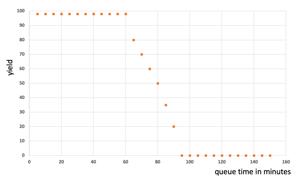
Based on the shown graph there is clearly a cliff starting after 60 minutes of queue time. The process team will very likely request from the manufacturing team that lots never wait longer than 60 minutes at in this zone. To be on the safe side the request might even be max. 45 minutes.
Lets have a look how such a time link zone is typically defined:
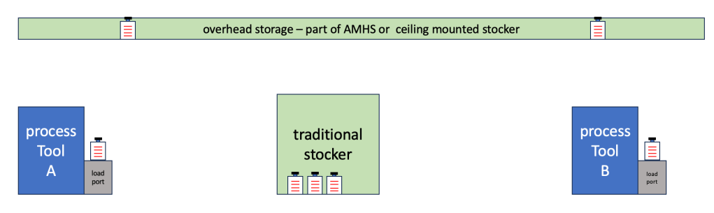
Time link zones are typically defined by a zone between a “trigger step” and the “target step”. The trigger step is the step in the process flow where the time link zone starts. A typical definition can be:
– the queue time starts, when the lot receives a operation complete – meaning all wafers at the trigger step on process tool A are completed and back in the carrier. The time would end when the lot receives an operation start at the target step on the target tool – in the picture above the process tool B.
The idea is that all the time the lot / carrier is spending in transport, waiting in storage locations is counted towards that maximum allowed queue time, which should not be exceeded.
How can manufacturing manage this ?
In a nutshell: a lot will be only started at the trigger step / tool, when there is a guarantee, that the lot can be started at the target step within the given time boundary (in my example 45 minutes). This sounds pretty simple, but involves a lot of calculations and scheduling.
- on how many tools can the target step be processed
- how much WIP is in front of the target tool group waiting
- how long is the transport time between trigger and target step
- are there other higher priority lots in the time zone
- … many many more
There are many different ways in the FAB to manage this – from simple KANBAN approached to neuronal network based solutions. All of them have on thing in common: protect the wafers from too long wait time between trigger and target step. In a nut shell: the WIP flow will be controlled, which typically means slowed down.
There are 2 points in a flow where this happens:
1. for all time link lots at the trigger step – it will only be released onto the trigger steps if the zone is “empty enough” – hence each time the zone is not ready – the lot will wait.
2. other lots waiting on the target tool, which are not in a time link zone ( on a different step in the flow) will have to give a time link lot priority – and therefore they have to wait even longer.
How big the overall impact on the FAB performance will be depends on a lot of things. Prominently these:
- shortness or length of the time link zone
- total number of different time link zones in a flow
- how risky the scheduler manages the time link zone
1. length of a time link zone
To define the “best length” is a tricky task. From a yield point of view shorter is better. From a manufacturing point of view longer is better. But not only that. In reality the yield degradation curves do not look that well defined like in the example from the top. Where to put the limit for the one below ?
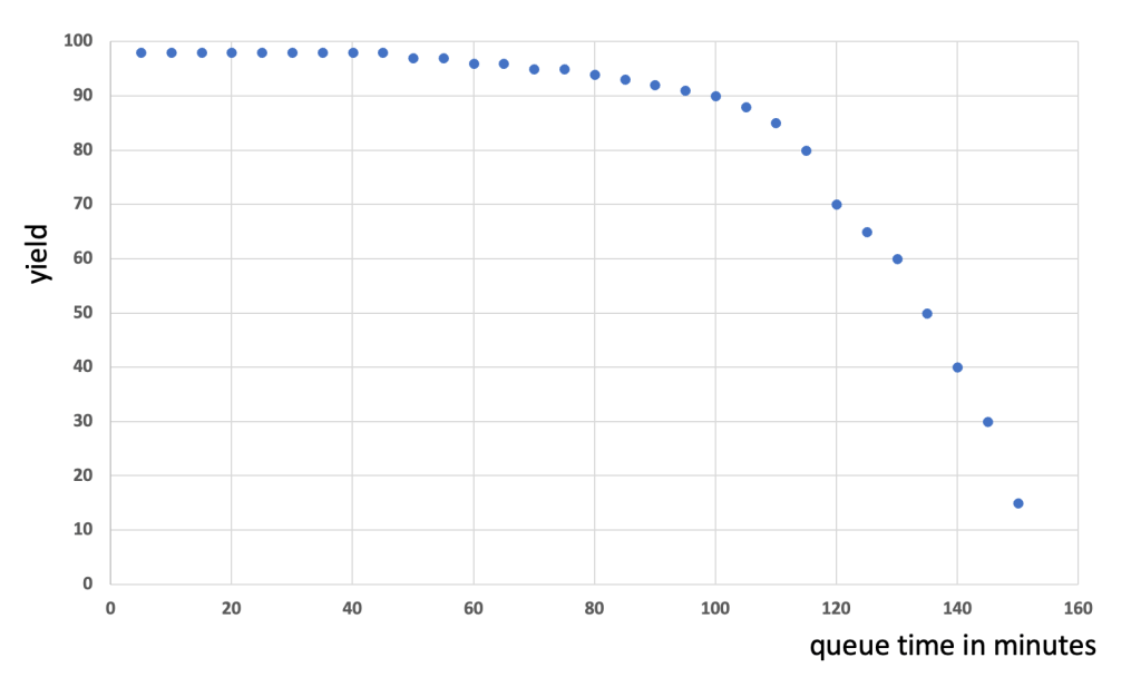
Set the max allowed time to 45 minutes to be super safe – but likely have massive WIP flow impact ?
Set it for example to 80 minutes and take a yield hit ?
Another interesting aspect is the definition of the start and end time of the time link zone itself. The above used method of operation start of the target step and the operation complete of the trigger step is often not good enough for very sensitive processes.
Technically, the “bad environment influence” on the lot starts when the 1st wafer of the lot is finished with processing at the target step and is back in the carrier waiting for the other wafers of the lot.
For this 1st wafer the queue time ends, when it is back in the process chamber of the target step. The definition of the time link zone would be then: process complete of the trigger step until process start of the target step – at wafer level – not the lot level !
To manage time links on wafer level is a much harder challenge.
2. total number of different time link zones in a flow
Managing a single time link zone can be challenging, but if there are multiple zones with multiple steps and tool groups involved – it can become a challenging mathematical problem very fast.
Rule of thumb: More zones, more challenges and more impact on FAB productivity
Most mature processes often have only 1 or 2 time link zones – usually in the gate oxide and/or gate poly steps. Advanced process flows can have hundred or more time link zones!
3. how risky the scheduler manages the time link zone
In complex time link zones is no 100% guarantee that all lots “make it safely” in time to the trigger step. Too many factors and their variability will prevent the perfect solution.
A simple example is: If a target tool goes down, while there is planned WIP for this tool in the time link zone.
Therefore most algorithms use settings to calculate the probability of a lot making it in time to the target step. And the settings for these depend on many factors, again.
Rule of thumb: the higher the probability is set (lower risk) the more impact on FAB performance
Summary
Any time link zone in a flow will have impact on the FAB performance – just by the fact that every once in a while a lot has to wait at a target step.
How much the impact is depends on how much the FAB is willing to “pay for” avoidance of impact. Payment comes in one or more of these “currencies”:
- plan with lower tool utilization to provide buffer capacity
- invest in advanced scheduling (software, server, people)
- invest in Nitrogen purged storage solutions to extend the possible queue time
for example: OHT or stocker purge upgrades LINK
A great additional source on the subject of managing controlled queue times is the
FabTime Newsletter: Vol. 24, No. 2: Managing Time Constraints between Process Steps in Wafer Fabs
LINK

Thank you for linking to my article, Thomas! I learned some new things from your write-up (I’d never thought about the impact on the first wafer through the target step, for example). I have shared it on LI and will include in my LI roundup in my next newsletter. My newsletter audience will certainly be interested.
LikeLiked by 1 person
Thanks for providing this good summary of the complexities around time links. Wafer-level management can often be avoided by assuming consistent processing durations at the trigger and target steps.
It just gets tricky when there is a process pause / abort in the middle of the lot.
LikeLike
Thank you for commenting- yes, the closer one zooms in on the topi the more tricky it gets !
LikeLike